Building a Bus Pirate
Back at the end of January, I entered one of the Dangerous Prototypes free PCB giveaways, and was luck enough to win a code. I've thought about getting a Bus Pirate for flashing microcontrollers etc., and building one seemed like a good project that would net me something useful at the end. So, here's the two-month-long saga of how I ended up with two Bus Pirates.
Obviously, the PCB needed components so while I was waiting for it to arrive from China, I put in an order with Digikey for the parts along with a few extras to get to the AU$60 free shipping point. This took far longer than I thought - while I've ordered components before, this was a bit more of a learning experience. For example, I knew that the same part often comes in different packages, but I didn't know that there are often multiple variations of the same package. I also found out that ceramic capacitors have a huge number of possible dielectrics which all have different tolerances over different temperature ranges.
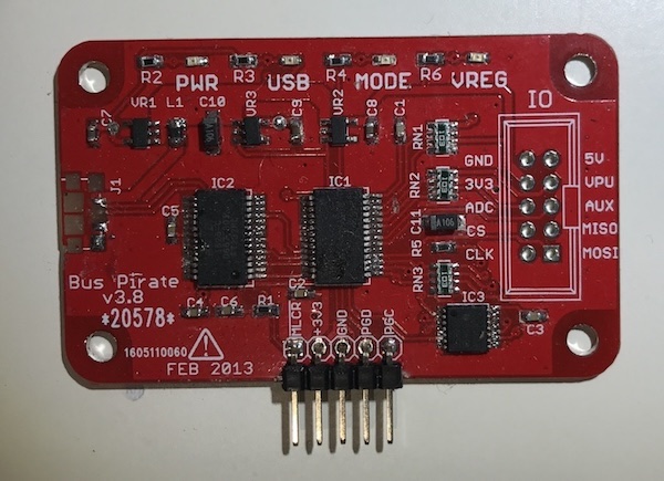
Once the board arrived, I got to soldering. This was the first time I'd done 0603 (1.6 × 0.8 mm metric) and SSOP packages, but with a lot of flux and some desoldering braid things went ok. Well, until I tried the surface-mount micro-USB connector. The first connector was the victim of too much solder, as it flowed into the socket and made it almost impossible for the jack to get in. After getting some replacement sockets, I tried again, but another failed attempts ended with me destroying the footprint:

It was around this time that I decided to see if it was worth salvaging the damaged board, given all of the 'work' I'd done on the USB connector. Getting the firmware onto the PIC microcontroller that's at the heart of the Bus Pirate requires a programmer, but having only done a little bit of work with AVR chips before, I don't have a PICkit and didn't want to buy one just for this project. Before ordering the parts, I'd seen a solution on the Dangerous Prototypes forums that used an ATmega and some Windows software (which was later updated), but couldn't get it to talk to the ATmega. Given may failure to solder the USB jack and flash the firmware, I mentally scrapped the project and bought a Bus Pirate v3.6 from a Polish seller on eBay.
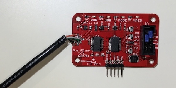
The story should probably have stopped here - after all, I had a working Bus Pirate now - but of course, I couldn't resist trying to flash the Bus Pirate I'd been building, just to see if it worked. This was super-simple, as I just hooked up the two Pirates together and used picprog to flash the combined bootloader/flash image. Since this went perfectly, it seemed a good bet that everything apart from the USB connection was working, so I set about trying to repair this. For my first attempt I tried scraping off the soldermask and attaching thin copper wire to the 'new' pads, but this left em with the same problem I'd had with the USB socket. However, in trying this I did (finally!) realise that the socket wasn't really necessary since its purpose was to provide a connection to the computer. Drawing from the massive supply of A-to-B cables I had lying around, I soon had a donor cable ready to go, and after carefully scraping away more soldermask was able to attach the wires to the PCB.

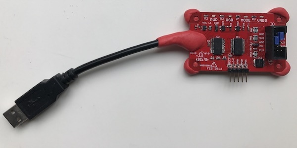
Despite all of the abuse I dished out and the less-than-perfect soldering job, the LEDs lit up and when I connected to it, the self-test passed. The next step was to add insulation and strain relief using some Sugru that I'd had in the fridge for a few years. I didn't think it'd still be any good, but it moulded well and cured properly, making a strong connection for the cable and a neat way to lift it a bit off the desk.

So now the only thing I have to work out is what on Earth I can use two Bus Pirates for.